Introduction
This tutorial will explain to you in great detail how to build your own AcidMods SpitFire 360 Wired Controller. The modded SpitFire 360 controllers can be programmed to turn a pistol into a semi automatic or to help you hit all kinds of combos you could probably never master on your own.
Required Items:
1: 30 awg Kynar Wire
2: Solder, soldering iron and paste
3: Dremel with cut off wheel
4: Hot Glue Gun and Glue
5: 18 pin Socket
6: 2 X 22pf Capacitors
7: 4 MHz crystal
8: .1uf Capacitor
9: 2 momentary Buttons
10: 1 momentary Buttons
11: Proto PCB from RadioShack
12: 1 X 3mm or 5mm LED
13: 3 X 10K ohm resistors
14: 1 X 4.7K ohm resistor
15: PIC16F84A
A plethora of parts most of what is needed here can be found at www.Imagesco.com ----->Parts-27 $9.95(Parts Only)<----- You can also buy the pic programmer there if you want to make your own code but if not you will later be able to buy all the different chips for different games there as well..
Part One: Adding Socket:
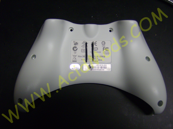
1. Cut two slots for the feet of the socket to go through the battery pack for this location you can only use the rechargeable batteries and you will later find out you will need to cut the AA terminals off of the I/O board of the controller.. You will most likely need to grind down the inside of the battery pack so you can see the feet as you will need to solder wires to them..
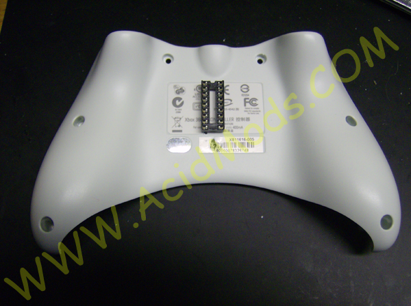
2. Carefully check the feet to make sure you have enough sticking out the other side to bend them down that will hold the socket in place allowing you to solder to the pins without worry of the socket falling out.
3. Once positioning is good solder a 30 awg kynar wire to each of the 20 pins. After the pins are soldered pump a lot of hot glue over the wires. Allow the glue to cool for five minutes. You will now notice that the wires are protected in a nice plastic shell preventing them from getting pulled accidentally.
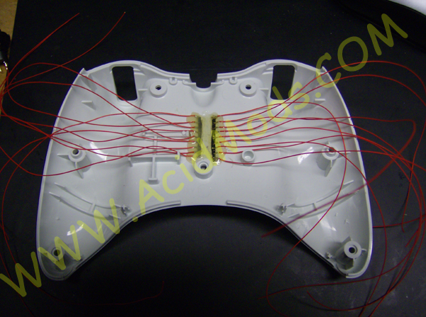
5. I also lined up the wire so they are very low profile it is not important to use different color wires as we can just check them for continuity later as we go..
Part Two: Adding Buttons:
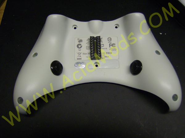
Adding the buttons to the controller is fairly strait forward just make sure you pick buttons that suit your need and fit well in the controller. I choose big red ones so I had to remove the rumble motor quick connects and solder the motors strait to the I/O board.
You want to drill two equal holes so you can control 2 macro's like "Automatic Pistols in Halo" and "Shotty blast switch to pistol and three burst fire." this will make for some interesting combo's..
This is what your bottom half of the controller should look like when you are complete. If you made it this far the hard part is over. The rest is just simple soldering to traces and component feet.
Here is a quick reference of the button circuits we will go into detail later on the entire wiring of the chip I just posted this here as a quick reference. Sometimes it is easier to break large circuits into smaller ones as it is easier to wire in sections as not to forget something.
Drill a small hole for either a 3mm or 5mm LED. This LED will be used as an indicator LED letting you know what setting you have programmed. I used a 5mm red LED for my controller. I used hot glue to hold the LED in place. You can install your led in a more discreet location as not to arouse suspicion.
Like the LED you will need to drill a hole for a sub miniature momentary switch. This switch is how you will switch between stored functions on the micro controller. Like the LED you can mount this switch in any location you wish.
Here is what the under side looks like use hot glue to keep LED in place..
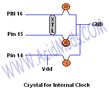
Part Three: Making the Crystal for the Internal Clock
You will need to cut a small section of proto PCB for a location to mount the Clock crystal. We want to do this to prevent the components from rattling loose. Once we have the board cut we will need to solder the 4 MHz Crystal, the two 22pf Capacitors and the .1uf capacitor..
Here is the basic wiring diagram for your Crystal this will be soldered to pins 15 and 16 and connected to ground. This is important as the chip will not work without it connected correctly. you may design your board any way you wish or use raw wire as long as the pathway is as the diagram shows....
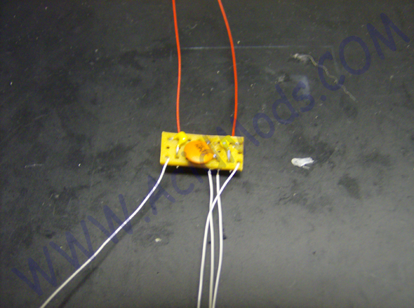
Here is my board I tried to make it Small then I encased it in hot glue to prevent it from grounding. You can make yours any way you wish as long as it follows the design.
Also, here is a blow up view the crystal is on the other side..
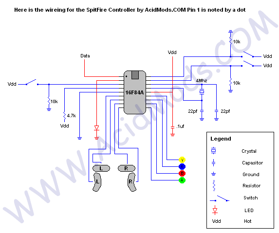
Here is the internal wiring for the 360 SpitFire 360 controller. With this diagram you should be able to complete the controller portion of the mod next step is getting the chip needed for Xtreme Gamming.
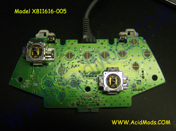
Step Four: Pinouts for the controller
1: Left Trigger 2: D-Pad Left 3: D-Pad Down 4: D-Pad Right 5: D-Pad Up 6: Select 7: 360 Dome 8: Start
9: X Button
10: Y Button
11: B Button
12: A Button
13: Right Trigger
14: Right Shoulder
15: Left Shoulder